The difficulty in the DARPA Grand Challenge lies in the uncertainty that abounds throughout autonomous urban driving. The distinct focus of the MIT team explicitly addresses this uncertainty in all aspects of our system, ranging from sensing to planning to control.
Sensing
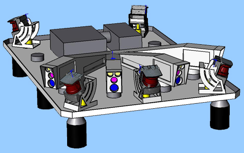
The roof-mounted sensor rack
Our vehicle perceives the state of the environment using state of the art hardware including LIDAR range finders together with vision sensors and its own motion through the combination of GPS and an IMU.
Laser Range-Finders
The LIDAR suite includes "push-broom" sensors for analyzing the neighboring terrain along with a complementary 360 degree system for obstacle detection and tracking. Several of the push-broom range finders are downwards-facing at different angles that allow us to infer critical aspects of the terrain. Additionally, we augment these scanners with vertically-oriented LIDARs that the vehicle uses to fuse the push-broom data into a 3D mesh that we use to identify drivable terrain. Meanwhile, a ring of laser range finders located around the vehicle form the obstacle detection system. Objects that lie above the ground plane are identified and tracked over time by utilizing some of MIT's recent research in robust state estimation. The system predicts future trajectories for each target that are then used to plan the vehicle motion.
Camera System
The LIDAR suite is supplemented with a vision system capable of detecting static and moving obstacles, identifying the drivable road surface, and locating road markings. As the schematic to the left shows, the platform utilizes a forward-looking narrow field-of-view camera (yellow) for far-field perception together with several wide angle cameras (red) for sensing within shorter ranges. While the laser range finders are critical to navigation in the near field, the vision system provides us with long range sensing that allows the vehicle to travel safely at maximum speed.
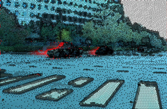
In order to drive at maximum speed, the vision system must be able to detect and track obstacles of varying size and shape beyond the range of LIDAR. We address the problem with a broad, low-level approach based upon optical flow. The system estimates the motion field over a set of features within the image and infers the depth of corresponding images in the scene. Obstacles are then identified by comparing the motion field to the image space velocities of the ground surface. The vision system then estimates the velocity of each obstacle based upon its intersection with the ground plane and tracks its movement over time. The algorithms take advantage of novel optical flow research conducted at MIT, and are robust to the uncertainties common to urban environments. Click on one of the links to the right to view a video that demonstrates the application to a street scene.
Planning
The Mission Planner develops high-level plans based upon the input route network and mission specifications. The algorithm, in essence, utilizes a shortest-path search for which the edge costs in the search tree are updated online using information from the Perception Module. This allows the planner to account for contingencies such as blocked roads and to re-plan as necessary. Due to the dynamic nature of the environment, we incorporate a time-dependent weight on the information that is used to update the search tree. This strategy provides us with an evolving framework for planning. For example, what once were obstructed routes eventually appear to be traversable, allowing the vehicle to re-explore the environment. Such flexibility is likely to be critical to achieve the missions in a dynamic environment.
The Situational Planner refines the high-level plan to generate the reference trajectory that is tracked by the low-level controller. The trajectory is dynamically feasible and stays clear of all static and dynamic obstacles. Critical to this task is the Perception Module that senses and detects the obstacles that may interfere with the short-horizon trajectory of the vehicle. A combination of optimization and interpolation-based planning is used for the different phases of lane following, maneuvers, and parking.
Control
The actual driving is handled by the vehicle's control system, which, given the reference trajectory from the Situational Planner, commands the steering and throttle accordingly. The new Urban Challenge presents several new design challenges as city driving requires a greater level of control sophistication. Specifically, we are developing a coordinated brake and throttle system that produces smooth adjustments to vehicle speed while also allowing for slow stopping maneuvers, such as at a stop sign or traffic signal. This feature was largely ignored (and unnecessary) in the previous challenge. Additionally, the urban challenge requires the completion of parking maneuvers. Autonomous parking necessitates a controller for driving in reverse, a challenge few, if any, teams addressed in the previous DARPA Grand Challenge. This is a particularly interesting controls problem as vehicles exhibit unstable dynamics while in reverse. Ultimately, both of these features will be integrated into a controls package which results in smooth, fluid driving.